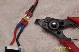
The only mod needed to the connector is to drill a #50 hole in both sides of the connector system but be careful to drill so you miss both metal blades. I find if I nestle the drill into the radius at the surface level change it works very well.

It has really helped to not be pulling on the wires and when the connector lets go, your hand smashes a wing or some other vital part of your pride and joy.
Iafret’s Solution for Unplugging
Dean’s Ultra Connectors

I will let the photos do most of the talking because it is so simple;
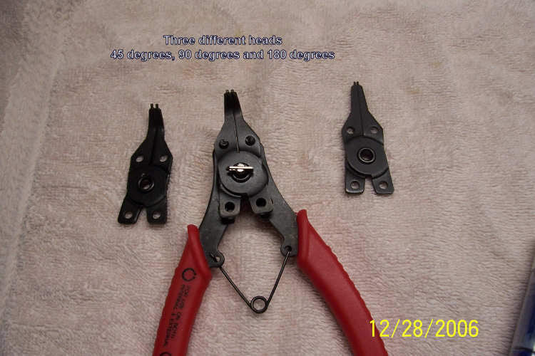
First, run out to your local auto parts store and buy an E-Ring tool. I got this one at Auto Zone for about $10.00 and it comes with three heads to allow you to get into difficult places if the connector is in the plane. (Saw one at Harbor Freight the other day for under $5.00)
TIPS
Click for PDF Version

BUILD LOG FOR THE MICKEY’S BIG TIMER

Introduction and design parameters:
Our club, The Greater Detroit Soaring and Hiking Society has a good and varied membership that fly F3K, ALES, F5J and TALES. We run 4 events per year in each of the three disciplines (we lump ALES and F5J together for scheduling) and each discipline has its own CD. We also have a shed at our field that we keep equipment in year around but when the club decided to spend the money on the MBT we also decided that it could not be stored in the shed with its great temperature swings and critters that kind of like the place. It was apparent that the MBT had to be very transportable and self-contained as possible because each of the three CD’s would be sharing and lugging the thing home and back to the field almost weekly.

As I naively volunteered to build the enclosure before I knew it had to be transportable it fell on me to do some head scratching (it hurts because of the lack of hair) and build an “everything-in-one-box” system. What I came up with is here in picture form and as few words as I can muster to make it clear.

We did opt for the pre-ship assembly by Mickey and that took a lot of work out of the process and I would advise anyone purchasing this unit to do the same. Mickey was more than gracious answering my questions and talking me through fixing my mistake when the MBT did not work on first try. I did not read the instructions he emailed me carefully enough so if you communicate with him, listen.

Things I purchased or had laying around:
What I did not have in my shop I got on AMAZON or at the local hardware store and here is the list as best I remember.

Bow and Arrow case: Amazon Link

Hookup wire (100 feet): Amazon Link

Banana Plugs: Amazon Link (I had 10 female sets on hand so did not purchase these but they are also on Amazon)

Plastic Corner Molding: 2X8’ lengths from Home Depot (the cheap semi-clear flexible plastic)

100 4MMX8MM machine screws from the local ACE HDWE store

16”X24”X 0.090” Clear Acrylic Plastic sheet from Home Depot

16 or so feet of 3/4”x3/4”x1/8” Aluminum Angle from the local ACE HWDE store

3M Automotive Trim Tape (large ½ wide roll) from the local Auto Zone

4- ¼” dia by 3 foot long fiberglass rods we “up-north fokes” use to mark the driveway for the
snow removal guys.

Goop (love this stuff) and some assorted wood screws.

XT60 connectors

Scrap plywood and hardwood I had laying around to make the temporary stand. (we have not decided how we are going to display the unit on the field as yet)

Plastic box to house the “Contest Controller” (swiped from my wife’s collection of stuff)

The Build:
Most of the detail will be shown on the photos. It is not a step by step but I am sure you will get the idea and probably improve on it.

The build sequence I used was:

Print out Mickey’s instruction from the Dropbox files

Lay out the parts and hook up all the wiring, it is almost idiot proof if you get the pre-assembled kit. Most of the wiring will ‘kind of’ all line up so it is just go along and plug stuff together.

Measure everything and go to the Hardware and Amazon stores and get stuff.

Assemble both displays with the aluminum angle plus little plastic squares on the big display.

Update all the software from Mickey’s Dropbox files and hook up the system to do an “It all works” test. Make sure you have enough power as the displays take a lot (11 amps total at 12V) and this is important… THE CONTEST CONTROLLER ONLY USES 5V FROM A USB OUTPUT. Be very careful to have all the pluses and minuses hooked up correctly. Some of the display controller interconnects are a little fussy and close together so make sure you have no shorts and they are clamped down well.

Play with the Contest Controller (NOT HOOKED UP TO THE DISPLAY YET) until you figure out how to program a contest or trial contest (not hard but it is like getting a new phone or transmitter, you need to get familiar with it).

Hook up the Contest controller to the Display Controllers then hook up the power.

Block up the displays so you can see them, careful as the big display is not too stiff torsionally. Once in the case it is better but the case is plastic and flexible also so just do not twist it a lot by picking it up in the corners, always handle it from the center handle.

Run the test, you may have to cycle the power once to get it to sync to the Contest Controller.

Build the protection for the back of the small display using the flat aluminum strip and the corner molding with 3M automotive trim tape and the acrylic sheet. I did this because the back of the large display will always be protected in the case but the small one is going to be out in the open. I am guessing it will be hanging in the wind somewhere near the scoring tent. I am thinking the small display power supply will need to have some cooling on hot days so I made the cover two pieces so that the one over the power supply could be cracked open a little to allow in cooling air. Also the small display controller may have to be updated with firmware once in a while so it the plastic panel on that end can also be slid off to allow access.

Fab up the base of the bow case to accept the large display. I used 4 standoff blocks of plywood about 1” square along the top and bottom to align with the aluminum angle. Then I screwed some bellcranks on the aluminum angles that were extended about 1.5” past the display. These then cammed in under four more wooden blocks I screwed and Gooped to the side of case. Just rotating the cam 45 degrees allow the large display to be removed for the display controller updates.

Using the yellow post hardware that came with the Plano Case I fabricated a couple of plastic disks and screwed them to the top of the short posts to hold the wiring.

Then I fabricated the “stand up” base out of scrap plywood and made a couple of wood recievers for the quarter inch fiberglass rods used to hold the lid up and keep the case from falling over when in use.

I used the arrow holders that came with the case to store the rods and just used padding for the storage of the take-apart stand.

Photo Documentary...

Download the PDF for complete document...

SPOILER HOOK-UP
BY: Ray Dinoble

This is the cleanest spoiler hook-up I have seen to date. It is simple enough that anyone can figure it out just by looking at the three photos.

Thanks Ray for another cool trick.